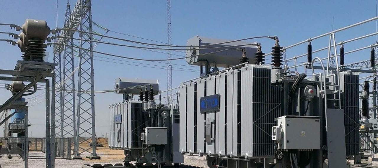
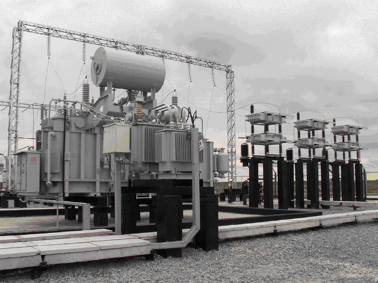
Controlled shunt reactors (USR)

Appointment
Currently, FACTS (Flexible Alternative Current Transmission Systems) devices – controlled equipment for AC power networks-are widely used in the global electric power industry. The use of FACTS devices allows you to quickly and efficiently manage active and reactive power flows.The controlled shunt reactor (usr) is a new type of FACTS device that has been widely used since the late 90's for voltage stabilization and control of reactive power flows both in main and distribution networks and at the level of large industrial consumers.In combination with a battery of static capacitors (BSC), the controlled reactor performs all the functions of static thyristor compensators (STC). In contrast to the traditional STC circuit solution, which consists of a communication transformer, series-connected reactors and a counter-parallel thyristor valve at full power, the usr has only a specific transformer device, in which the role of the reactor is performed by the inductors of the windings, and the role of the counter – parallel thyristor valve is a saturated rod. As a result, instead of three power elements, there is one. At the same time, the usr does not require the installation of high-power filters of higher harmonics to ensure the quality of the voltage.
The purpose, efficiency and composition of usr equipment for distribution networks (110 kV and below) and for inter-system communications (220 kV and above) are somewhat different. Networks of 110 kV and below. Usr is mainly used in parallel with static capacitor banks in branched networks with a strong load and a load that is sensitive to the voltage level (for example, asynchronous load)

For 220 kV and higher networks. Usrs are effective on intersystem power lines with reverse flows of active power and a sharply variable load schedule. At the facilities where hydroelectric power stations are issued, the operating modes of which provide for the possibility of deep daily and seasonal regulation

Based on the tasks solved by the usr, the scope of their application extends (but is not limited to) the following areas of electric networks:
networks with a sharply variable load schedule;
networks with worn-out switching and transformer equipment that is often used to regulate voltage levels;
networks formed by long transits that tend to frequently change the magnitude and / or direction of power flows;
networks that supply consumers with high requirements for voltage stability;
high-loss networks;
networks whose operating mode does not allow the permissible load of generators for
reactive power.
The wide functionality of the usr provides the feasibility of their use at various voltage classes. At the same time, the expected effect can be manifested both at the level of the local area of consumer networks, and when solving priority tasks of the national energy system as a whole.
In the context of the formation of market relations in the electric power sector and increasing investment in the development of electric networks, usrs offer a number of significant benefits for all economic entities:
at the level of main and distribution electric networks, usrs provide a significant reduction in electricity losses;
at the consumer level, usrs are installed in order to stabilize the required voltage level, as well as as necessary measures for connecting new capacities to the network;
along with reducing losses and automatically stabilizing the voltage at the connection point, controlled reactors also provide a sharp reduction in the number of switching switches and RPN, an increase in the limits of active power transmitted along the lines, optimization of reactive power flows and unloading of generators from its consumption.
The principle of operation (basic characteristics)
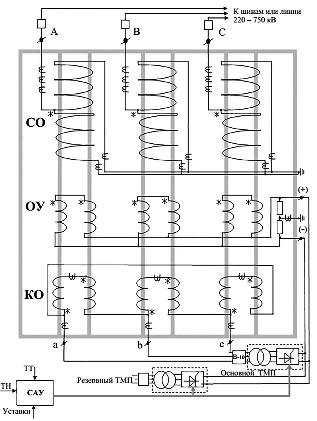
The principle of operation of controlled reactors with magnetization is similar to the operation of a magnetic amplifier. Smooth regulation of the reactive power consumed by the reactor over the entire range from idle to rated power is provided by saturating the working rods of the magnetic system on which the reactor windings are located with a constant flow, which is caused by a rectified current in the control winding. The higher the current in the control winding, the more saturated the magnetic core rods are and, accordingly, the lower the inductance and resistance of the network winding located on the rods. For explanation, the electromagnetic circuit of the three-phase three-winding usr of the RTU series is shown below.

Electromagnetic scheme of three-phase three-winding usr:
ACS-automatic control system; TMP-transformer with
Converter for magnetization; CO – network winding; OU-control winding;
CO-compensation winding
The AC voltage applied to the primary winding causes the corresponding AC flux in the core and the current of the network winding. Applied to the control winding, the constant magnetization voltage from the TMP causes a constant current in it and a corresponding constant flow in the core, which, as it increases, shifts the alternating flow to the steel saturation region, which causes a decrease in the inductance of the primary winding and an increase in the AC current consumed by it. The nominal half-limit saturation mode occurs when the total rod flow is located beyond the bend of the magnetization characteristic for half the period of the network frequency (180 El. deg). In this mode, there are no higher harmonics and the current consumed by the reactor is sinusoidal.
 |  |
Inductions of half-rods, CO and OP-AMP currents (left), current in CO, CO and OP-AMP (right) in the process of
setting the reactive power consumed by the reactor from idle to the nominal
value.
The compensating winding of the reactor with its connection in a triangle ensures the closure of the third harmonic (and multiples of it) in it, which reduces the content of higher harmonics in the consumed current over the entire control range to values below 3% of the rated current. In addition, the transformer of the main TMP is connected to the outputs of the co.
Design
As can be seen, the magnetic system of the electromagnetic part and the design of the usr-500 phase, the magnetization-controlled reactor differs in design from a three-phase three-winding transformer of comparable power only by splitting the working rods of each phase and the presence of a low-power TMP (1 MVA) with an automatic control system. Transformer technology of manufacturing and operation of conventional oil-filled equipment allows you to significantly simplify and reduce the cost of both manufacturing and operation of usr.
The compensation winding is located first on the half-rods, then the control winding, and the network winding connected to the star is located external to them.
TMP consists of two identical oil-filled tanks,one of which houses a 10/0. 4 kV supply transformer, the other-a thyristor Converter made according to the Larionov scheme. The only element located in a closed room is the automatic control system (ACS), which provides automatic voltage stabilization modes or maintains the level of reactive power consumption set by the dispatcher.
 |  |
Magnetic system of three-phase usr of the RTU series with a voltage of 500 kV | Design of the usr 500 kV phase |
The main advantages of CSR with magnetic biasing
The main advantages of controlled shunt reactors include their high reliability, best technical and economic performance, structural similarity with conventional transformer equipment, and ease of operation.
Special training of service personnel and creation of additional working conditions at the installation site are not required for the operation of the usr. Do not use water cooling or place equipment in closed rooms (as in the case of solutions based on STK). An additional advantage of the usr is that it can be connected directly to high-voltage buses and there is no need to use step-up transformers. This allows you to provide the entire adjustment range of the reactor at exactly the voltage class where it is necessary for the operating mode of the electric network.
Operational experience and efficiency
The operating experience of controlled shunt reactors has fully confirmed the high consumer qualities of this type of device. The usr installation provides continuous automatic control of optimal voltage levels at a number of distribution substations in a large area of electric networks. At the same time, the cost of maintenance and repair of transformer and switching equipment that takes an intensive part in the process of voltage regulation is sharply reduced.
The efficiency and payback of installing controlled reactors or replacing SHR with usr largely depends on the choice of their installation location and on the characteristic modes of the adjacent electrical network. So, for example, the installation of the first RTU-25000/110 type usr in 1998 In the Northern electric networks of Permenergo (at the Kudymkar PS, in parallel with the existing capacitor Bank) paid off within three years only by reducing losses due to jet power flows along long overhead lines from the power center at the maximum daily loads and in the opposite direction during their minimum hours. Even more characteristic is the installation of three such usrs in the North of the Tomsk region at substations that feed drilling rigs. Only due to a sharp decrease in the collapse of the drilling load during the thunderstorm period, their payback period was only one year. In less obvious cases of such effects, the payback period of the usr is from 5 to 10 years. For example, the installation of a RTU-180000/500 type usr at the Tavrichesky MES of Siberia, along with voltage stabilization and optimization of flows along transit lines, reduced the number of switching operations of unmanaged SHR installed on the PS by dozens of times a year.
